
'TM Electronic Exhaust-Valve Systems' - TMEES 1 & 2
MAINTAINING YOUR TMEES-1 (CABLE) & TMEES-2 (ROD) SYSTEMS
125cc / 144cc / 250cc / 300cc – TMEES 1: ‘Cable Operation’: Fitting & Setting Of New / Existing Cables
It is advised that the following procedure relating to the set-up and maintenance of your TMEES Engine is used as per instruction on a regular basis to ensure both the performance and reliability of your TM Moto machine is maximised. It should be noted that TM UK recommend the procedure for the cable operated ‘TMEES 1’ systems be applied to your machine at 4 hours intervals for MX machines and prior to each event for Enduro machines.
NOTE: Do not loosen the 10mm hex-head nut that fixes the cable/rod pulley on TMEES systems to the cylinder either during cable replacement or to remove the cylinder during piston changes, remove the servo unit and remove the cable nipple from the pulley leaving the pulley tight in position on the cylinder. The nut, pulley and power-valve blades are set in a ‘timed’ position, releasing the tension on the nut will allow this ‘timing’ to be altered and if not re-set correctly will lead to poor performance and engine failure. Further instructions on setting the pulley / blade timing can be found below.
Please Click On The Link Below To Download The ‘TMEES 1’ Cable Operated Set-Up Guide.
‘TMEES 1’ Set-Up Instructions
The above instruction manual has been translated by the TM Moto staff into English, therefore some of the wording will seem unfamiliar, please see below for an altered translation of the numbered procedures.
NOTE: The servo unit only needs to be removed from the machine to replace the cables, for simple maintenance and cable adjustment the servo unit can stay attached to the cylinder brace but with it’s two fastenings bolts loosened slightly to allow some movement whilst performing the cable adjustment operation. The domed Allen Key headed bolt in the black moulded plastic cover on the servo unit can be removed to give access to the 4mm positioning hole for locking the servo arm ‘pulley reference’ hole into place prior to cable adjustment. If the 4mm ‘pulley reference’ hole in the servo arm is not inline with the 4mm hole in the servo unit’s black moulded plastic cover the servo can be moved by gently rotating the cable arm on the cylinder, this will allow the cables to pull on the servo arm rotating the 4mm ‘pulley reference’ hole into the correct position for a 4mm locking pin to be inserted. It is advised that the 4mm ‘tool’ used to lock the servo arms ‘pulley reference’ hole to the covers 4mm positioning hole be slightly tapered to ease insertion. Do not loosen the 10mm nut fixing the cable pulley to the power-valve mechanism in the cylinder. Releasing the nut, and therefore the pressure on the shaft the power-valve blades are fixed to, with allow the blades to move independently and out of correct alignment and ‘timing’ of operation leading to poor performance and engine failure. Please see below for the settings of the power-valve blades and the measurements of.
- 1: Cables fitted in the correct position.
- 2: Cable with red sheath (2012/2013) / blue sheath (2014) / red+blue or clear sheath on 250cc/300cc models (2015) fitted into the lower position.
- 3: Cable tensioner locking nuts wound back fully allowing the tensioner adjuster to be screwed fully into the servo unit allowing maximum cable movement (fully ‘slack’).
- A: 4mm hole in the servo arm used to lock the servo into place for correct cable adjustment.
- 4: Black moulded protection cover in place and secured using the 6 screws.
- 5: Servo Unit installed onto the cylinder brace with the cable tensioner adjuster locking nuts wound back fully with the tensioner adjuster wound fully into the servo unit allowing maximum cable movement (fully ‘slack’).
- 6: Pulley reference 4mm positioning hole in the black moulded plastic cover inline with 4mm ‘pulley reference’ hole in the servo arm, please see ‘NOTE’ above for instructions on aligning the two holes with the servo unit fitted in place on the cylinder brace.
- 7: 4mm ‘tool’ inserted into black moulded plastic cover positioning hole and into 4mm ‘pulley reference’ hole in servo arm, this locks the servo into the correct position for cable adjustments to be set.
- 8: fixing the two cables to the cylinders exhaust valve pulley arm.
- 9: Remove the cylinder’s black moulded plastic cover to expose the cylinder exhaust valve pulley arm and cable housings. Lock the cylinder exhaust valve pulley into place using another 4mm ‘tool’ allowing it to pass through the exhaust valve pulley arm and into the 4mm positioning hole located in the cylinder, this secures the cylinder exhaust valve pulley into the correct position prior to cable adjustment (cylinder exhaust valve pulley 4mm locking hole shown in ‘Figure 4’)
NOTE: both the cylinder exhaust valve pulley arm and the servo units pulley arm must both be locked into position to adjust the cables correctly.
- 10: Adjusting the tension of the pulley cables by means of winding the tensioner adjusters screwed into the servo unit outwards (anti clockwise) removing the ‘slack’ from the cables.
NOTE: The correct tension of the two pulley cables is set thus, remove the upper cable from it’s machined recessed housing in the cylinder and hold it over its housing, whilst pushing the black sheath of the cable gently rearward to ensure the cable is pushed fully home into the cable tensioner adjusters on the servo unit simultaneously wind the tensioner adjuster outwards increasing the tension until the cable sheath’s silver cap at the cylinder end is 1.0mm over the fitting face (2012>2013 machines), this ensures the correct cable pre-loading is set. The cable sheath can then be pulled gently backwards and pushed into the machined recessed housing that secures it. Repeat this procedure with the lower cable. Please try to ensure the cables are running from the servo to the cylinder in as straight a line as can be achieved, this can be assisted by moving the servo on it’s elongated mounting holes. Do not over-tighten as this will cause premature wear of the cables.
IMPORTANT NOTE: On the 2014 125cc / 144cc machines (cable with the blue sheath and the previous generation of TMEES-1 pulleys) and 2015 125cc / 144cc / 250cc / 300cc machines (red/blue cables and clear sheathed cables and last generation of TMEES-1 pulleys) is it advised that the tensioning procedure above is applied but the amount of tension itself should be reduced, the cables themselves once fitted should move relatively easily if squeezed between the thumb and finger, giving a more visible ‘loose’ setting ( of around 3mm of cable movement up/down) than that compared to the 2012>2013 system. The electronic system on the 2015 onward machines also automatically tests the system once the engine is started or it can be manually tested using the PDA (Diagnostic) plugged into the wiring harness connection port or with the TM Moto battery cable into the ‘condenser’ connection port (TM Moto Part No’ 68193 for ‘condensor port’ connecting type cable, Part No’ 68192 for PDA port type connecting cable) using a 12v motorcycle dedicated low amperage battery – the same type used on TM Racing electric start models.
- 11: Once the correct tension has been set on the pulley cables the locking nuts on the cable tensioner adjusters of both the upper and lower cables can be wound clockwise against the servo unit body and tightened locking the cable tensioner adjusters into place, please ensure the the cable tensioner adjusters are held securely in position whilst tightening the locking nuts to avoid accidental cable adjustments.
- 12: Remove the two 4mm ‘tools’ used to lock both the servo pulley arm and the cylinder exhaust valve pulley arm into place during cable tension setting.
- 13: Refit the domed Allen Key headed bolt into the pulley reference positioning hole in the servo’s black moulded plastic cover.
- 14: Refit the cylinder pulley black moulded plastic cover and replace the 3 fastenings Allen bolt securing it into place.
- 15: Re-tighten the servo units two fastenings.
- 16: Reinstall the 4 rubber protection ‘boots’ on the two pulley cables into their correct positions to minimise water and dirt ingress into the cables and operating system.
TMEES Cylinder Cable Pulley – Positioning & Resetting After Removal Of The Pulley
IMPORTANT NOTE: During any removal and / or re-fitting of the TMEES cable pulley on the cylinder there are several ‘set-up’ and positioning requirements for the limitation of movement allowed for the actual power-valve blades within the cylinder. These settings must be applied for the power-valve operation to function correctly .
- With the nut loose and with the power-valve blades moving loosely on the shaft you can now begin to set the positioning of the blades.
- To set the maximum opening position of the power-valve blades you must first insert the 4mm holding tool into the cable pulley and into the locating hole behind (as per setting cable tension) to lock the pulley into its ‘maximum’ position. using two fingers (one on each power-valve blade) push the blades as far as possible into the roof of the exhaust port (wide open), now tighten the nut on the end of the cable pulley shaft, the maximum opening position is now set.
- To set the minimum position firstly remove the 4mm holding tool to allow the cable pulley / power-valve blades to move up and down freely. Using a vernier measure form the top of the cylinder (with the cylinder head removed, directly down the side of the exhaust bridge) to the leading edge of one of the pulleys, this needs to be set to the measurement given below for each model.
- If you need to adjust the power-valve blades to achieve the given measurement you must use the adjuster on the cable pulley to set this. Loosen the locking nut and adjust the screw in either direction required to achieve the correct measurement, once achieved the locking nut can be re tightened, you can then double check your measurement is correct.
- The cylinder can now be re-fitted to the engine.
Measurements for the TMEES Power-Valve Blades in the ‘Closed’ Position.
- 125cc MX Models – 38.50mm
- 125cc Enduro Models – 39.50mm
- 144cc MX/Enduro Models – 41.50mm
- 250cc MX/Enduro Models – 57.30mm
- 300: MX/Enduro Models – 57.30mm
IMPORTANT INFORMATION: The new TM Moto TMEES engine is a high performance competition engine and it is recommended that the larger carburettor main jet sizes are fitted immediately during running-in and for initial ‘hard runs’ to give yourself a base setting. As there are so many variables with carburetion settings it is advisable that the possibility of being too ‘rich’ on fuelling is better than being too ‘lean’.
This latest generation of TM Moto 125cc engine with the electronic exhaust-valve operation is ‘all new’ and needs to be treated as such, therefore all known carburetion settings that were employed in the previous engine design are to be discarded, it is advised that a new program of education in fueling this new engine is devised as it’s required fuel quantities at various rpm stages have altered, this shows in the differing needle designation and position and jet sizes.
Please be advised to start with larger main jet sizes and decrease as required, not the other way round. Correct fueling of any 2-Stroke engine is of the uppermost importance to ensure correct performance and reliability, please ensure that conditions, temperature, elevation and rider ability is taken into consideration when carbureting your machine. Remember that an engine running on a harder surfaced circuit on a warm day will require different fueling to the same engine on a loose surface circuit on a colder day.Please be advised that is up to you to ensure that you machines engine is running correctly, checking the spark plug during every ride will soon inform you of any changes that may need to be made to your machines carburetion for the conditions. It is advised that you carry a selection of carburetor jets suitable for you machine which will allow you to make any changes should the need arise.
NOTE: Incorrect carburetion will lead to poor performance, bad running and even engine failure.
PLEASE NOTE: All advisories are for assistance only, you must test and set your machine to the given conditions, Super-unleaded fuel must be used at all times pre-mixed to the correct oil ratio of 33:1 – 40:1 (600ml / 500 ml of quality synthetic oil to 20 Litres of fuel), please be advised that conventional ‘regular’ unleaded does not meet the higher octane requirements of competition engines and it’s use will lead to poor running and even engine failure.
NOTE: Please ensure correct fueling at all times, regularly check the engines spark plug colour to ensure your engine is running within the correct parameters, please also take notice of the spark plug advisory relating too temperature. If the machine appears to be running incorrectly please rectify the carburetion or if you cannot do this please stop using the machine immediately and seek advice from your TM Moto dealer.
IMPORTANT NOTE: Never power-up any Servo / Powervalve control system motor without the system being fixed in place with any cables / rods attached and set on the cylinder in an operating position, this applies to all systems, whether cable, rod or direct drive operated (2025 ES engines). The ‘torque sensing; systems used to find the ‘limits of movement’ for correct operation will be exceeded and will allow the servo/motors to exceed their operational limits leading to possible damage and then incorrect functioning.
TMEES: Instructional Videos
TMEES – Cylinder Pulley Positioning:
tmees-settings
This video shows, using a cut-away cylinder, how the pulley must be locked in place using the pin holes used for cable adjustment, the power-valve blades pushed and held fully to the roof of the cylinder, and then, the nut tightened. This ensures that when the pulley is fully open the power-valve blades are open fully also.
TMEES – Power-valve Blade Measurement
tmees-settings-max-blade-adjustment
This video shows how to measure the travel of the power-valve blades using a vernier caliper. Each model has a specific measurement that the power-valve blades must ‘close’ from the fully open position, these measurements can be found in the text above. Measuring just off centre from the exhaust bridge the ‘closing’ measurement can be found, this can be adjusted using the threaded adjuster bolt on the pulley, once set correctly the locking nut on the adjuster bolt can be tightened. Re-measure after locking to ensure the measurement is still correct.
TMEES 1 & 2: TESTING AND RESETTING ELECTRONIC SYSTEMS
TMEES 1 ‘Cable Operatied’ Test and Reset Procedures:
125cc / 144cc – 2015>2019
250cc / 300cc – 2015>2018
For the 2015> models there are also built in programs in the electronic systems that will allow a ‘setting operation’ to be performed on the ‘TMEES 1’ (cable) systems using an outside power source with a dead engine. This can be performed after adjusting or fitting new cables on ‘TMEES 1’ systems or performing service work on the engine itself on either ‘TMEES’ systems.
This testing and resetting procedure will require the use of a ‘test cable’ or ‘diagnostic port connection cable’.
TM Part No’ 68193 – for test cable operated systems that will plug into the capacitor port ( TMEES 1 )
TM Part No’ 68192 – for systems on the 125cc / 144cc / 250cc / 300cc machines that plug into the wiring harness PDA port. ( TMEES 1 / TMEES 2 ).
TM Part No F08376 – The 4-stroke and 2-Stroke ECU interface cable, also come with a diagnostics port connection cable (like 68192) that can be used to perform TMEES tests and also on 2T Fi models for fuel pump priming.
There are different test and procedures for both capacity, carb or 2T Fi (Two-Stroke Fuel injection) variants. Please refer to the user manual for the correct machine to be able to perform the required test.
NOTE: You will also require a 12v motorcycle low-amperage battery – A TM Moto electric-start system battery for example, this is of course if the machine in question does not already have electric-start and a battery to take power from.
IMPORTANT NOTE: Do not use a vehicle battery (car or larger) to power the TMEES System, the high amperage output of these larger batteries will cause irreparable damage to the electrical system.
To test and reset the TMEES system you must first access the system by connecting the correct cable into the wiring harness. Either by the capacitor connection port – by removing the green male connector from the female connector, or, by removing the cap on the wiring harness PDA port. Once you connect the appropriate cable to the appropriate connection the electronics will now automatically perform a procedure that will move the servo and power-valve system between fully open to fully closed and come to rest in its neutral pre’ engine starting position, it is advised to leave the cylinder TMEES cover off whilst this is being performed to watch the operation cycle and ensure it has been completed. This setting operation will only take around 30 seconds to perform and once the operation has terminated, and the servo has stopped moving the cable system, remove the cable/battery and re-fit the condenser/capacitor connector. All other components can now be re-fitted to the machine prior to starting / riding. Do not forget to plug the capacitor lead back into its port or refit the PDA cap depending on type.
VIDEO: A Video Demonstration of Powering the TMEES System by Battery Can Be Found In The Video Section Below. NOTE: Only on 2015> models and using the capacitor port or the correct cable/fitting for the PDA (‘Palm’) connection into the main wiring harness.
Please ensure the power-valve cables are treated as per any other cable. Ensure frequent lubrication of the cables by either a penetrating spray or a designated light cable oil. Also periodic changing of the cables is advised, as with any cable under load, and whilst in a harsh environment, it will eventually fail, if the cable shows any sign of corrosion or fraying of the cable wire strands please replace the cable immediately.
TMEES – Powering The TMEES System Using The Diagnostic Port.
Click for Video
This video shows how to power the TMEES system, on 2015 onward models, for operational check and system set after fitting new cables. This can be done using the OBD port and the TM Moto PDA or by using the TM Racing cable plugged into the Condesor port and powering using a 12 volt motorcycle specific battery. Once connected the system will take a few seconds to respond upon which it will then cycle the power-valve opening and closing procedure and then return to the ‘closed’ position, at which time you unplug the PDA / Battery – Model Year & Type Instructions bel
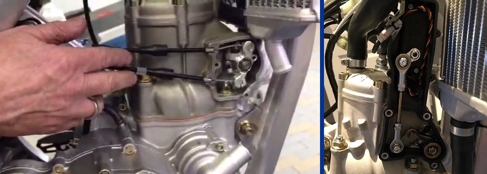
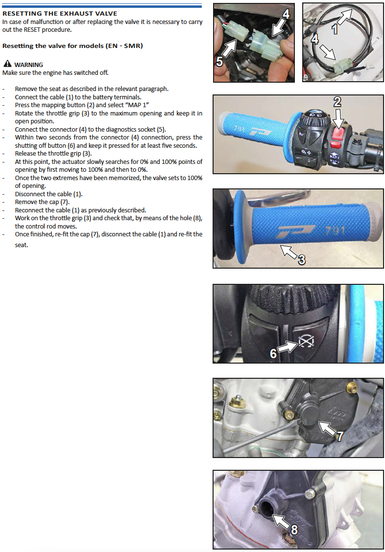
TMEES-2: ‘Rod Operated’ Electronic Exhaust-valve System Testing:
NOTE: There are different testing procedures for both Carburettor and 2T Fi (Two-Stroke Fuel injection variants) and the engine capacity, depending on model year. Please refer to the user manual relating to your machine to be able to perform the required test, different models will require a different procedure to perform the test. This can be found in the user manual. There is an image of the required page in the manual below this text section for the testing procedure for 2T Fi models.
TMEES-2 Test: 2020>2024 – 25cc / 2020>2025 – 144cc Engines with Carburettor
1) Power the TMEES-2 and ECU system using the PDA (diagnostic) port with the appropriate cable (TM Moto Part No’ 68192) and the correct power source – a 12v low amperage dedicated motorcycle battery as used by the TM Moto electric start system. Connect the cable (68192) into PDA port and the system will perform the test automatically.
After around 4 seconds after connection the system will start the self-storing operation which consists of 3 steps:
1. The exhaust valve is moved to the closing point
2. The exhaust valve is moved to the max. opening point
3. The exhaust valve is moved again to the closing point.
Now the system is ready. Disconnect the cable (68192) and remount the protective cap onto the PDA port.
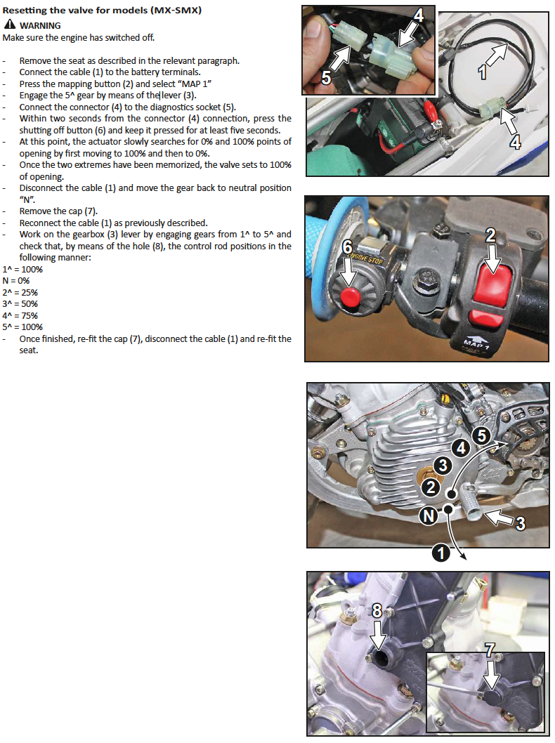
TMEES-2 Test: 2019 Onward: 250cc / 300cc Engines with Carburettor.
Please follow Initial set-up to ensure the procedure is completed correctly, please ensure the following steps are applied
- 1) RPM = 0 (engine off)
2) Map 1 position selected on mapping switch
3) 5th gear engaged
Activation of the electronic set-up procedure:
- 4) Power the TMEES-2 and ECU system using the PDA (diagnostic) port with the appropriate cable (TM Moto Part No’ 68192) and the correct power source – a 12v low amperage dedicated motorcycle battery as used by the TM Moto electric start system. Connect the cable (68192) into the TM PDA port and be ready to perform step 5 immediately.
IMPORTANT NOTE: DO NOT use a vehicle battery (car or larger) to power the TMEES System, the high amperage output of these larger batteries will cause irreparable damage to the electrical system.
- 5) Within 2 seconds of powering the system (point 4) you must depress the stop (kill switch) button – holding it down for at least 5 seconds. At this point the system activates and the servo slowly searches for the maximum and minimum opening points (0% – 100%) of the opening
first going to 100% then to 0%. Once the 2 extremes have been memorized, the valve is positioned at 100% – fully open valve.
Disconnect the cable that powered the system and return the gearbox to the neutral position. The procedure is terminated.
Reconnecting the power cable it is possible to make an approximate check
of correct operation as follows: With the engine off, engage the gears (1 – 5) checking that the valve is positioned as
described in the mirror below – earlier TMEES 2 250cc / 300cc models only.
- 1st = 100%
- N = 0%
- 2nd = 25%
- 3rd = 50%
- 4 = 75%
- 5 = 100%
IMPORTANT NOTE: Never power-up any Servo / Powervalve control system motor without the system being fixed in place with any cables / rods attached and set on the cylinder in an operating position, this applies to all systems, whether cable, rod or direct drive operated (2025 ES engines). The ‘torque sensing; systems used to find the ‘limits of movement’ for correct operation will be exceeded and will allow the servo/motors to exceed their operational limits leading to possible damage and then incorrect functioning.
PLEASE NOTE: On models equipped with a gear position sensor (mapping altered in the lower gears) that the TMEES system will not operate to 100 percent of its travel whilst in ‘neutral’ or the lower gears whilst the engine is running. When testing the TMEES system / or if running the machine on a stand and ‘watching’ the functionality of the TMEES system under engine power you must remove the drive chain from the engine to the rear wheel, select 3rd gear and then test. This will allow the electronics to give full operational travel to the servo system that would not normally be permitted whilst in Neutral/lower gears.
TMEES-2 Test: 2020>2024 – 125cc / 2020>2025 – 144cc / 2020> 250cc / 300cc Engines with Fuel Injection.
Powering the TMEES-2 and ECU system using the PDA (diagnostic) port with the appropriate cable (TM Moto Part No’ 68192) and the correct power source – a 12v low amperage dedicated motorcycle battery as used by the TM Moto electric start system.
IMPORTANT NOTE: DO NOT use a vehicle battery (car or larger) to power the TMEES System, the high amperage output of these larger batteries will cause irreparable damage to the electrical system.
Please follow Initial set-up to ensure the procedure is completed correctly, please ensure the following steps are applied – Image below.
TMEES Test: 2025> – 125cc Fuel Injection / Carburettor.
TMEES test / calibration procedure for 2025> Models using the eM103 ECU (Firmware 1.06) – for example the 2025 125cc E-Start engine models. Powering the TMEES system using the PDA (diagnostic) port with the appropriate cable (TM Moto Part No’ 68192) and the correct power source – a 12v low amperage dedicated motorcycle battery as used by the TM Moto electric start system.
Engine off:
Engage 3rd gear.
Open the throttle fully and keep it in this position (not needed on carburetor models)
Power the electrical system from the diagnosis socket and wait at least 6 seconds.
The valve calibration procedure will begin (This lasts a few moments).
At the end of the procedure, return the vehicle to its original condition.
IMPORTANT NOTE: DO NOT use a vehicle battery (car or larger) to power the TMEES System, the high amperage output of these larger batteries will cause irreparable damage to the electrical system.
IMPORTANT NOTE: Never power-up any Servo / Powervalve control system motor without the system being fixed in place with any cables / rods attached and set on the cylinder in an operating position, this applies to all systems, whheter cable, rod or direct drive operated (2025 ES engines). The ‘torque sensing; systems used to find the ‘limits of movement’ for correct operation will be exceeded and will allow the servo/motors to exceed their operational limits leading to possible damage and then incorrect functioning.
Please follow Initial set-up to ensure the procedure is completed correctly, please ensure the steps are applied.